Effective collaboration is the key to translating a design “problem” or “challenge” into a formalized plan for building or renovating a structure. In order for a project to meet all of its objectives, everyone involved must be able to visualize the design parameters, understand the design task at hand, and compare design solutions in terms of functionality, cost, constructability, and aesthetics.
To enable stakeholders to immerse themselves in the details of projects, we rely on a specific set of software tools and systems:
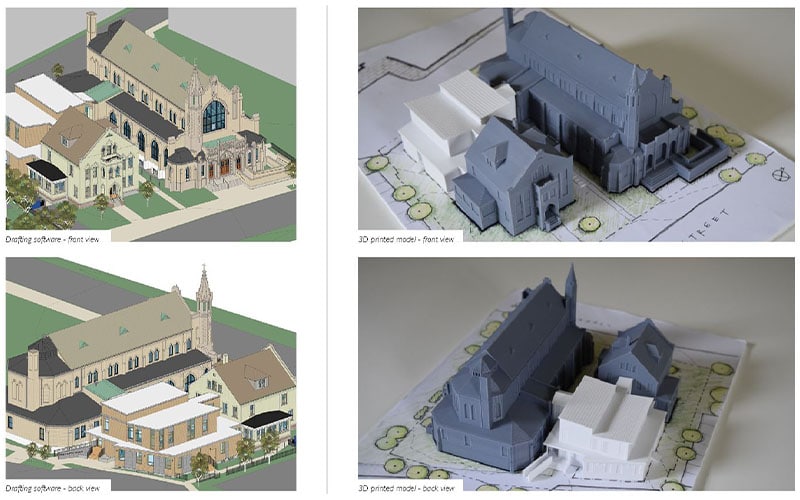
- Autodesk Revit. This is modeling software we use to create 3D images of an existing or proposed building or space. Later in a project, we also use Revit to coordinate construction activities.
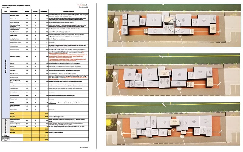
- Excel. We use this spreadsheet software, with which most people are familiar, to organize program areas and requirements early on. This information is then translated into “bubble diagrams” and blocks for spatial organization studies.
- 3D printing. We use a 3D printer to produce physical models of the designs we’ve created.
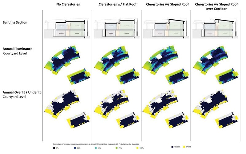
- Sefaira. Using Sefaira, we determine how our design will be affected by changes in daylight—throughout a given day and as the seasons change.
- Lumion. Used with Revit, Lumion creates realistic images, video walk-throughs, and 360-degree panoramas.
We leverage these tools in a series of steps that takes the project from rough concepts to a finished design.
From Ideation to Realization
While every project is unique, generally speaking we go from idea to completed construction or renovation following some or all of these 10 steps:
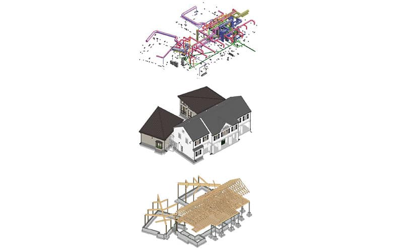
- Visualizing existing conditions. When a project site has existing structures, it’s critical that we produce an accurate 3D representation of their sizes and relative locations for use in developing our design.
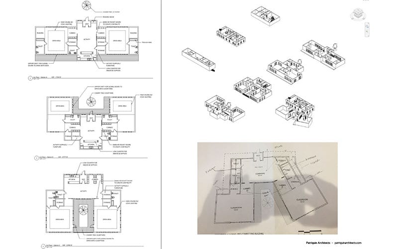
- Programming and space planning. In order to create a design, we first need a complete list of the spaces that will be needed and the attributes of each, including their size, working clearances, any special considerations for utilities, and any guidelines from national, state, or local authorities. As we gather this information, we use blocks and bubble diagrams to begin developing layouts.
- Concept planning studies. What we learn in step 2 is the foundation for developing basic architectural plans and layouts. Characteristics like entry and egress points, circulation, and general wall thicknesses are factored into these studies.
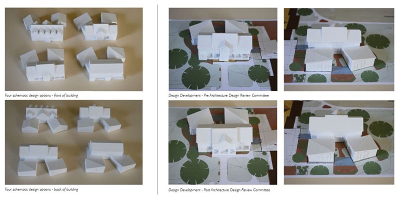
- 3D massing studies. Our designs begin to take physical (if miniaturized) form in this step with the help of a 3D printer. The models are used both by our team and for client work sessions.
- Daylighting. How will a structure’s lighting, energy usage, and other factors be affected by the position of the sun throughout the day and from one season to the next? The answers from our daylighting studies are important to the success of the project.
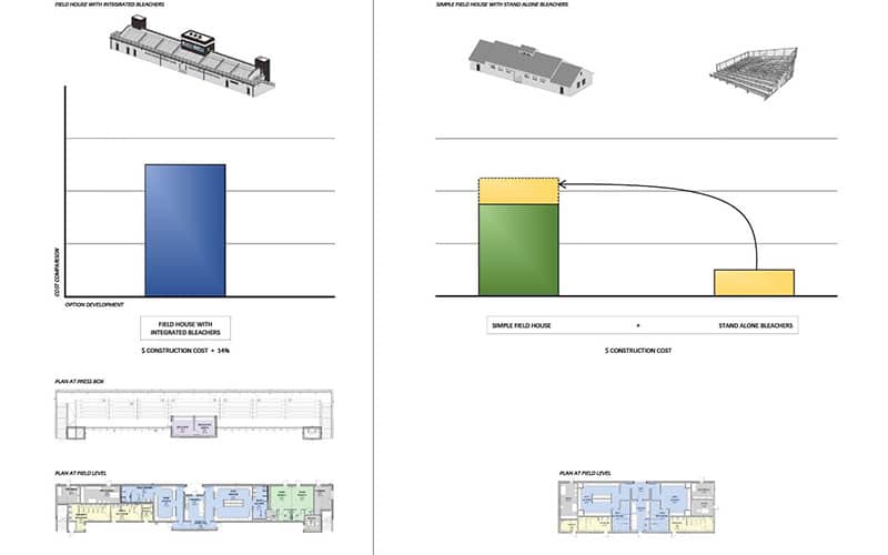
- Options development and analysis. In this step, we produce multiple options that help the client understand how the aesthetics, efficiencies, and costs of a project can be manipulated.
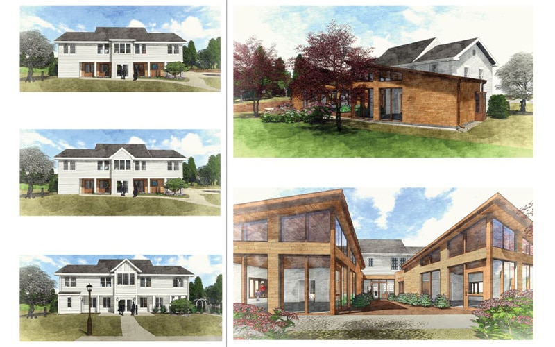
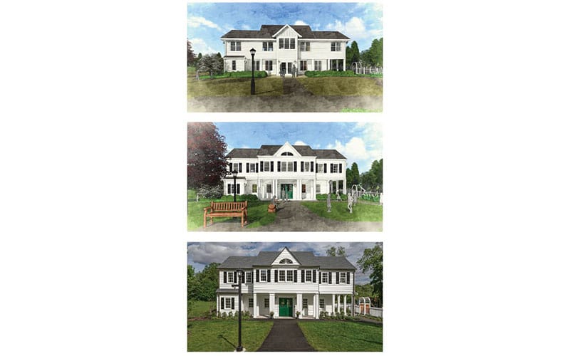
- Visualizing materials and fenestration. How will materials like roofing and siding, and the arrangement of doors and windows, affect the appearance of a building? Rendering software helps us show the client different options.
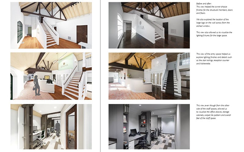
- Envisioning finishes and lighting. How the rooms in a building are finished (paint colors, architectural accents, etc.) and the type and location of light fixtures are very important, both in terms of aesthetics and functionality. In this step, we explore some options.
- Regulatory approvals. Here we use all the resources we’ve developed to request the necessary approvals from government entities, architectural review boards, and other commissions. This typically requires presenting detailed exterior renderings to communicate the project.
- Project management and coordination. All of the contributors to projects we manage – structural, mechanical, electrical, and plumbing engineers, in particular – use the same software (Autodesk Revit) for developing their design. This enables us to undertake a process called “clash detection” where we merge our models to see if there are any conflicts, and if so, resolve them. This is much more efficient and cost-effective than discovering problems after construction is underway!
A Time-Tested Approach to Sharing the “Big Picture”
Nobody likes to invest time, effort, and money in the hope that a project will meet their expectations. Helping clients and other stakeholders see a project evolve from concept to detailed plan before construction begins gives them confidence that the completed structure will be what they had envisioned.
If you would like to learn more about our process or have a project you want to discuss, please contact us at your convenience. You can also check out projects we’ve completed in our online portfolio.